|
Profinet EIP EtherCAT
EGD UDP RFM RtEthernet Tc-net S7 Modbus OPC iso Ads Siemens
AB,GE,Mitsubishi,Beckhoff,MOOG,Schneider,ABB,Alstom,Driver,Domestic
PLC,Special Board QDR quality data
recording (digital steel coil) centimeter and millisecond level, supports
32+clients online Equipment testing, fault
diagnosis, quality analysis, ikoPDA CHPDA PLC-PDA, No crack & call
similar system |
3rd PDA formats &
Rich proprietary features Global Standards,
Exceptional Value Simplified for Full Customization &
OEM with Open APIs Proven by Hundreds of |
|||||||||||||||||||||||||||||||||||||||||||||||||||||||||||
|
Process Data
Acquisition �C PLC-PDA -- Detailed analysis of
quality manage & industrial big data sources -- Full stack develop & Fully intellectual property
owned |
||||||||||||||||||||||||||||||||||||||||||||||||||||||||||||
|
46 |
||||||||||||||||||||||||||||||||||||||||||||||||||||||||||||
|
47 |
||||||||||||||||||||||||||||||||||||||||||||||||||||||||||||
|
56 PDA system scheme for converter, RH furnace, LF furnace in
steel plant |
||||||||||||||||||||||||||||||||||||||||||||||||||||||||||||
|
64 S7-1200 as
both a PROFINET IO Controller and an IO Device |
||||||||||||||||||||||||||||||||||||||||||||||||||||||||||||
34 Rockwell AB PLC
When the programming environment and authorization are repeatedly installed abnormally, uninstall all installed programs, delete all folders C: Program Files (x86) Common Files Rockwell, C: Program Files (x86) Rockwell Software, C: Users Public Documents Rockwell Automation, and reinstall them. If any service programs are occupied, stop the service first. 34.1 Connect Rockwell PLC
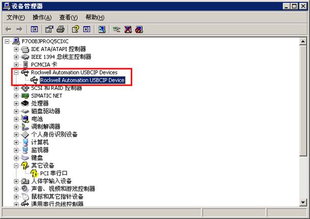
with USB
Connect the USB cable (USB2.0 port) from the PLC to the PC, and the driver will be automatically installed.
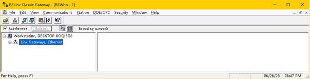
Opening RSLinx Classic gateway will automatically detect AB_ VBP-1
Right click to install an unknown device driver.
34.2 Set
the IP address of the Ethernet communication module
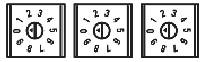
The first method is to use a rotary switch to set the network IP address Usage conditions: (1) Module with rotary switch (2) The target IP address is in the 192.168.1.xxx network segment Some of Rockwell's Ethernet communication modules come with rotary switches, as shown in the figure below for the 1756 EtherNet/IP communication module. The switch positions vary depending on the module.
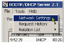
When powered on, the module will read the rotary switch data to determine whether the last part of the IP address value is valid. The valid numerical range is 001... 254. If the set value is valid, the following situations will occur: IP address=192.168.1.xxx (where xxx represents switch setting) Subnet Mask=255.255.255.0 Gateway Address= In general, it is recommended to set the rotary switch to a valid value before installing the module. However, if the target IP address you want to set is not 192.168.1.xxx, you can use the following method Set the rotary switch to an invalid value, and then use the second method to set the IP address. The second method is to use a BOOTP/DHCP server to set the network IP address Usage conditions: (1) The module does not have a rotary switch and has BOOTP/DHCP enabled. (2) The module has a rotary switch but the set value is invalid, and the module has BOOTP/DHCP enabled. BOOTP/DHCP server is a standalone server used to set IP addresses. You can use a BOOTP/DHCP server to set IP addresses and other Transmission Control Protocol (TCP) parameters. Access the BOOTP/DHCP server from the following location: Programs>Rockwell Software>BOOTP DHCP Server Before starting the BOOTP/DHCP server, ensure that you have obtained the hardware (MAC) address of the module. The hardware address is on the sticker on the side of the communication module, in a format similar to 00-BC-14-55-35. Specific steps: (1) Start the BOOTP/DHCP software. (2) Select Network Settings from the Tools menu.
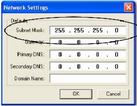
(3) Enter the subnet mask for the network. The gateway address, primary DNS address and/or secondary DNS address, and domain name fields are all optional items.
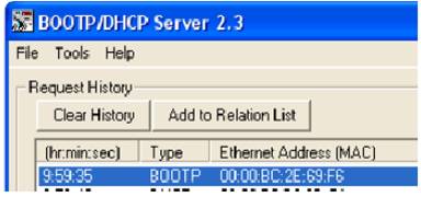
(4) Click OK. The Request History panel will appear, with BOOTP issued The hardware addresses of all requested modules. (5) Select the appropriate module.
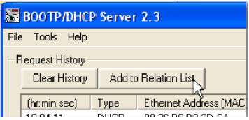
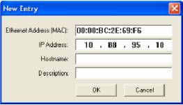
(6) Click Add to Relationship List. The New Entry dialog box will appear.
(7) Enter the IP address, host name, and module description information.
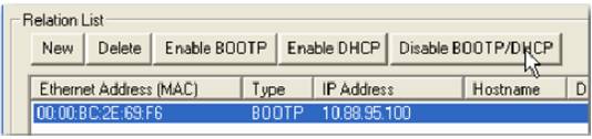
(8) Click OK. (9) To permanently assign this configuration to a module, wait for the module to appear in the Relationship List panel and then select it. (10) Click on Disable BOOTP/DHCP. After cyclic power on, the module will use the assigned configuration without issuing a BOOTP request. If Disable BOOTP/DHCP is not clicked, after cycling power on, the host controller will clear the current IP configuration and issue a BOOTP request again.
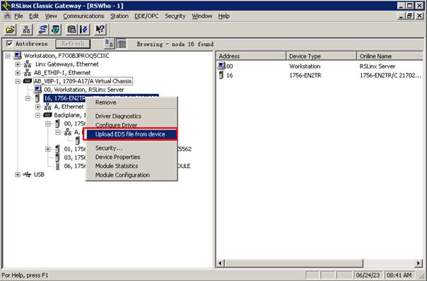
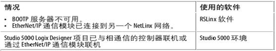
The third method: Use RSLinx software or Studio 5000 environment to set the network IP address
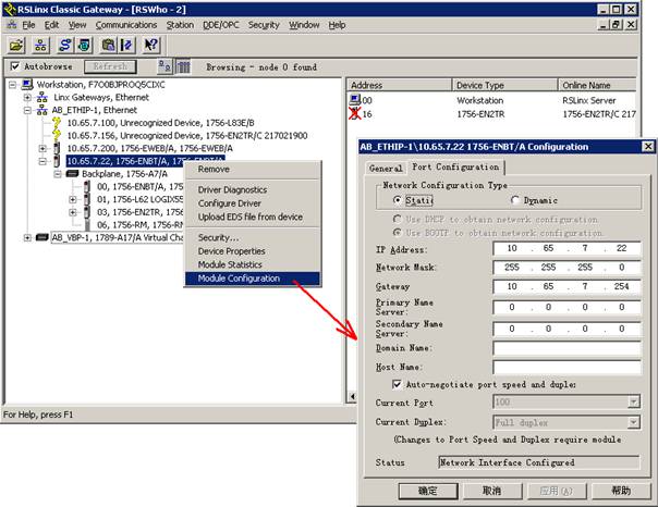
The specific steps to set the network IP address using RSLinx software are as follows: (1) Select RSWho from the Communications menu and the RSWho dialog box will appear. (2) Connect the PLC using Ethernet. (3) Right click on the EtherNet/IP module and select Module Configuration. The Module Configuration dialog box will appear. (4) Click on the Port Configuration tab.
34.3 Connecting
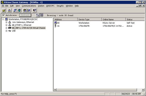
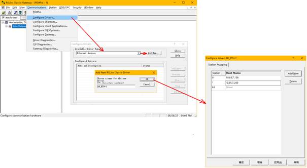
Rockwell PLC with Ethernet
PLC cannot be automatically scanned.
Add communication protocol and IP address of PLC.
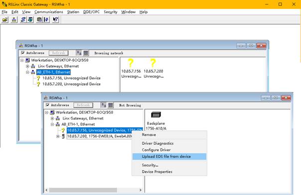
It is easy to scan to the PLC and update device drivers.
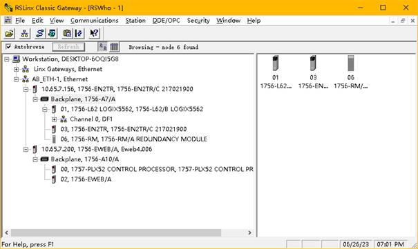
The equipment and communication are both normal.
34.4
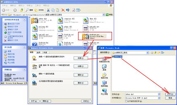
Installing RSLinx Classic Gateway Authorization
Run the virtual floppy drive simulation program WinVF.exe, load the authorization impression file gzhstar.img, and run Move Activation -32 Bit to move the relevant authorization from the floppy disk to the hard disk partition. 34.5
Install programming tool RSLogix authorization
34.6
EtherNet/IP
EtherNet/IP (EtherNet Industry Protoco1) is a protocol system suitable for industrial environment applications. It is the latest member launched by two major industrial organizations, ODVA (Open DeviceNet Vendors Association) and ControlNet International. Like DeviceNet and ControlNet, they are networks based on the CIP (Control and Information/on Protoco1) protocol. It is an object-oriented protocol that ensures the effective transmission of implicit real-time I/O information and explicit information (including configuration parameter settings, diagnostics, etc.) on the network. EtherNet/IP adopts the same application layer CoCIP (Control and Information Protoco1) as DevieNet and ControlNet, therefore they use the same object library and consistent industry standards, with good consistency. EtherNet/IP uses standard EtherNet and TCP/IP technologies to transmit CIP communication packets. In this way, the universal and open application layer protocol CIP, combined with the widely used EtherNet and TCP/IP protocols, constitutes the architecture of the EtherNet/IP protocol. Rockwell, as a representative, supports ControlLogix CompactLogix MicroLogix and other series.
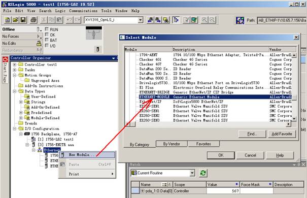
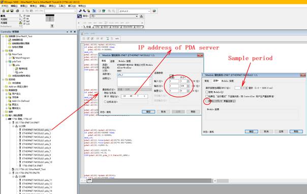
RSLogix example is follow, one connection may collect most 496 bytes, gather 124 real or 248 int or other type, 124REAL and 120REAL+128BIT are shown below. PDA sample period may be 2ms. Define User-Defined: TPDA1 as REAL [124] Define User-Defined: TPDA2 as REAL [120] +SINT [16]
Define two Tags: pda1 and pda2, respective data type is TPDA1 and TPDA2
Establish first connection, fill 10.65.7.216 into Host IP address, and define relevant tag: pda_1, the system automatically produces pda_1: C, pda_1: I, pda_1: O, above figure is shown.
Establish second connection, fill 10.65.7.217 into Host IP address, and define relevant tag: pda_2, the system automatically produces pda_2: C, pda_2: I, pda_2:O.
Create user��s program and define cycle period, call this task, fill collect signal into relevant position by serial number.
pda1.AI[0]:=pda1.AI[0]+1; if pda1.AI[0]>32000 then
pda1.AI[0]:=-32000; end_if; pda1.AI[1]:=sin(pda1.AI[0]*0.03)*1000; pda1.AI[2]:=cos(pda1.AI[0]*0.05)*1000; pda1.AI[3]:=1003.0; ...... pda1.AI[122]:=1122.0; pda1.AI[123]:=1123.0; COP(pda1.AI[0],pda_1:O.Data[0],496); pda2.AI[0]:=pda2.AI[0]+1.0; if pda2.AI[0]>32768.0 then
pda2.AI[0]:=-32000.0; end_if; pda2.AI[1]:=sin(pda2.AI[0]*0.02)*1000.0; pda2.AI[2]:=cos(pda2.AI[0]*0.02)*1000.0; pda2.AI[3]:=2003.0; ...... pda2.AI[118]:=2118.0; pda2.AI[119]:=2119.0; pda2.DI[0].0:=1; pda2.DI[0].1:=0; pda2.DI[0].2:=0; pda2.DI[0].3:=0; pda2.DI[0].4:=0; pda2.DI[0].5:=0; pda2.DI[0].6:=0; pda2.DI[0].7:=0; pda2.DI[1]:=1; pda2.DI[2]:=2; pda2.DI[3]:=3; pda2.DI[4]:=4; pda2.DI[5]:=5; pda2.DI[6]:=6; pda2.DI[7]:=7; pda2.DI[8]:=8; pda2.DI[9]:=9; pda2.DI[10]:=10; pda2.DI[11]:=11; pda2.DI[12]:=12; pda2.DI[13]:=13; pda2.DI[14]:=14; pda2.DI[15]:=15; COP(pda2.AI[0],pda_2:O.Data[0],496); The PDA server IP address can be set as follows: one network card can receive 2 messages, or multiple physical network cards can be used.
The data source type is 22, Config.csv of PDA server is below, One IP can only collect data from one connection: [1000,124CH,2.000ms,10.65.7.6,22,EthernetIP,10.65.7.216] No,
Name,Adr/note,Unit,Len,Offset
,Gain
,Type,ALM, CH1=, ,
, ,4 ,0.000000,1.000000,REAL,0 ,0.000,0.000,0.000,0.000,0 CH2=, ,
, ,4 ,0.000000,1.000000,REAL,0 ,0.000,0.000,0.000,0.000,0 CH3=, ,
, ,4 ,0.000000,1.000000,REAL,0 ,0.000,0.000,0.000,0.000,0 ���� CH123=, ,
, ,4 ,0.000000,1.000000,REAL,0 ,0.000,0.000,0.000,0.000,0 CH124=, ,
, ,4 ,0.000000,1.000000,REAL,0 ,0.000,0.000,0.000,0.000,0 [2000,248CH,2.000ms,10.65.7.6,22,EthernetIP,10.65.7.217] No, Name,Adr/note,Unit,Len,Offset ,Gain ,Type,ALM, CH1=, ,
, ,4 ,0.000000,1.000000,REAL,0 ,0.000,0.000,0.000,0.000,0 CH2=, ,
, ,4 ,0.000000,1.000000,REAL,0 ,0.000,0.000,0.000,0.000,0 CH3=,
,
, ,4 ,0.000000,1.000000,REAL,0 ,0.000,0.000,0.000,0.000,0 ���� CH247=, ,
, ,1 ,0.000000,1.000000,BIT ,0 ,0.000,0.000,0.000,0.000,0 CH248=, ,
, ,1 ,0.000000,1.000000,BIT ,0 ,0.000,0.000,0.000,0.000,0 Data source type 66 can also collect data in this way, a PDAServer IP can collect data from multiple connections. Sample period may be 2ms, Recommendatory sample period is more than 10ms, you can reduce data length above if less data point is collected. You may collect data by standard ethernet if WEB+ module is used, the scheme is not recommended due to complicated PLC��s program. 34.7
EtherNet/IP-backplate
Read the PLC data according to the variable name, no PLC program is needed, the data source type is 29 or 62, and the collection period is not less than 10ms. The collection program is d:\PDA\pdaCIPClient\pdaCIPClient.exe for 62 data source type, The PDA server side needs to install the VC++2022 runtime library, VC_Redist.x64.exe and VC_Redist.x32.exe. Supported PLC is Rockwell ControlLogix series. Global variables of Controller Tags can be collected, the PLC data type are BOOL, SINT, INT, DINT, REAL, STRING. Corresponding PDA data type are BIT, BYT, INT, DINT, REAL, STRING, STRING maximum is 82 characters. One dimensional array is supported besides STRING. Below is for configuration example, the ADDRESS column must be same as the variable name in PLC. [1000,46CH,10.000ms,10.65.7.21,29,Note,10.65.7.216,3] No, Name
,Adr/note
,Unit,Len,Offset
,Gain
,Type CH1=,
DiagMinTokHldTime_LSW,DiagMinTokHldTime_LSW, ,2 ,0.000000,1.000000,INT CH2=,
DiagTokHldTime_LSW
,DiagTokHldTime_LSW
, ,2 ,0.000000,1.000000,INT CH3=, ErrReConfig_ErrMasErr,ErrReConfig_ErrMasErr, ,2 ,0.000000,1.000000,INT CH4=,
ErrNotOk
,ErrNotOk
, ,2 ,0.000000,1.000000,INT CH5=,
abc[0]
,abc[0]
, ,4 ,0.000000,1.000000,DINT CH6=,
abc[1]
,abc[1]
, ,4 ,0.000000,1.000000,DINT CH7=,
abc[2]
,abc[2]
, ,4 ,0.000000,1.000000,DINT CH8=,
,
, ,4 ,0.000000,1.000000,DINT CH9=,
abc[3]
,abc[3]
, ,4 ,0.000000,1.000000,DINT CH10=,abc[4]
,abc[4]
, ,4 ,0.000000,1.000000,DINT CH11=,realarray[33]
,realarray[99]
, ,4 ,0.000000,1.000000,REAL CH12=,realarray[66]
,realarray[189] , ,4 ,0.000000,1.000000,REAL CH13=,strtest
,strtest
, ,20
,0.000000,1.000000,STRING CH14=,abc[5]
,abc[5]
, ,4 ,0.000000,1.000000,DINT CH15=,abc[6]
,abc[6]
, ,4 ,0.000000,1.000000,DINT CH16=,
,
, ,4 ,0.000000,1.000000,DINT CH17=,abc[7]
,abc[7]
, ,4 ,0.000000,1.000000,DINT CH18=,abc[8]
,abc[8]
, ,4 ,0.000000,1.000000,DINT CH19=,abc[800]
,abc[800]
, ,4 ,0.000000,1.000000,DINT CH20=,myBool[0]
,myBool[0]
, ,1 ,0.000000,1.000000,BIT CH21=,myBool[1]
,myBool[1]
, ,1 ,0.000000,1.000000,BIT CH22=,myBool[2]
,myBool[2]
, ,1 ,0.000000,1.000000,BIT CH23=,myBool[30]
,myBool[30]
, ,1 ,0.000000,1.000000,BIT CH24=,myBool[4]
,myBool[4]
, ,1 ,0.000000,1.000000,BIT CH25=,myBool[5]
,myBool[5]
, ,1 ,0.000000,1.000000,BIT CH26=,myBool[6]
,myBool[6]
, ,1 ,0.000000,1.000000,BIT CH27=,myBool[7]
,myBool[7]
, ,1 ,0.000000,1.000000,BIT CH28=,myBool[799]
,myBool[799]
, ,1 ,0.000000,1.000000,BIT CH29=,myBool[128]
,myBool[128]
, ,1 ,0.000000,1.000000,BIT CH30=,myBool[233]
,myBool[233]
, ,1 ,0.000000,1.000000,BIT CH31=,myBool[309]
,myBool[309]
, ,1 ,0.000000,1.000000,BIT CH32=,myBool[468]
,myBool[468]
, ,1 ,0.000000,1.000000,BIT CH33=,myBool[825]
,myBool[825]
, ,1 ,0.000000,1.000000,BIT CH34=,myBool[666]
,myBool[666]
, ,1 ,0.000000,1.000000,BIT CH35=,myBool[1000]
,myBool[1000]
, ,1 ,0.000000,1.000000,BIT CH36=,sintTest
,sintTest
, ,1 ,0.000000,1.000000,BYTE CH37=,sintarray[10]
,sintarray[10]
, ,1 ,0.000000,1.000000,BYTE CH38=,sintarray
[100]
,sintarray[100] , ,1 ,0.000000,1.000000,BYTE CH39=,
,
, ,4 ,0.000000,1.000000,REAL CH40=,sintarray[199]
,sintarray[199] , ,1 ,0.000000,1.000000,BYTE CH41=,realtest
,realtest
, ,4 ,0.000000,1.000000,REAL CH42=,realarray[50]
,realarray[50]
, ,4 ,0.000000,1.000000,REAL CH43=,realarray[99] ,realarray[99]
, ,4 ,0.000000,1.000000,REAL CH44=,
,
, ,4 ,0.000000,1.000000,REAL CH45=,realarray[189]
,realarray[189] , ,4 ,0.000000,1.000000,REAL CH46=,s1
,s1
, ,30
,0.000000,1.000000,STRING 34.8 EtherNet/IP-backplate block
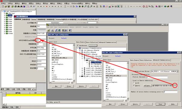
The data source type of 59 or 63. This method can collect a large amount of data from the PLC at a faster speed. There is no need to program communication in the PLC. The PDA actively reads the data block as a whole, and the supported PLCs are Logix, PLC5, and SLC.
The collection program is d:\PDA\pdaCIPClient\pdaCIPClient.exe for 63 data source type, The PDA server side needs to install the VC++2022 runtime library, VC_Redist.x64.exe and VC_Redist.x32.exe. VC++2022 runtime library and pdaCIPClient.exe do not need to be for type 59, but at most 3990 bytes can be collected. Define a structure TpdaBlockData in PLC, which gathers the signals to be collected into the variable pdaBlockData of the structure. The length of each data type block of the structure should be an integer multiple of 4 bytes, and the overall COP of pdaBlockData should be copied to the global sint array pdaBlock every scanning cycle. PDA efficiently collects data from pdaBlock, a data access path selected according to the above figure. The data flow is: individual data of various types -> pdaBlockData -> pdaBlock. The following table is an example of the structure TpdaBlockData.
The assignment statement in PLC is as follows. pdaBlockData.int16[0]:=pdaBlockData.int16[0]+1; pdaBlockData.int16[1]:=pdaBlockData.int16[0]+10; pdaBlockData.int16[2]:=pdaBlockData.int16[0]+100; pdaBlockData.int16[3]:=pdaBlockData.int16[0]+1000; pdaBlockData.int8[0]:=pdaBlockData.int8[0]+1; pdaBlockData.int8[1]:=pdaBlockData.int8[0]+1; pdaBlockData.int8[2]:=pdaBlockData.int8[0]+2; pdaBlockData.int8[3]:=pdaBlockData.int8[0]+3; pdaBlockData.s1[0]:=65; pdaBlockData.s1[1]:=66; pdaBlockData.s1[2]:=67; pdaBlockData.s2[0]:=70; pdaBlockData.s2[1]:=71; pdaBlockData.s2[2]:=72; pdaBlockData.s3[0]:=81; pdaBlockData.s3[1]:=82; pdaBlockData.s3[2]:=83; pdaBlockData.b1.0:=1; pdaBlockData.b1.1:=1; pdaBlockData.b1.2:=0; pdaBlockData.b1.3:=1; pdaBlockData.b1.4:=0; pdaBlockData.b1.5:=1; pdaBlockData.b1.6:=1; pdaBlockData.b1.7:=1; pdaBlockData.b2:=170; pdaBlockData.b3:=85; pdaBlockData.b4:=0; pdaBlockData.float[0]:=pdaBlockData.float[0]+0.01; pdaBlockData.float[1]:=sin(pdaBlockData.float[0]); pdaBlockData.float[2]:=cos(pdaBlockData.float[0]); if pdaBlockData.float[0]>1000.0 then
pdaBlockData.float[0]:=-1000.0; end_if; pdaBlockData.float[1000]:=pdaBlockData.float[1]; cop(pdaBlockData,pdaBlock[0],4088); The PDA configuration Config.csv is as follows. [1000,46CH,10.000ms,10.65.7.156,59,Test1,10.65.7.216,,,,,,,1.1]
No, Name
,Adr/note,Unit,Len,Offset
,Gain ,Type, CH1=,
int16
,no ,mm ,2 ,0.000000,1.000000,INT , CH2=,
int16
,
, ,2 ,0.000000,1.000000,INT , CH3=,
int16
,
, ,2 ,0.000000,1.000000,INT , CH4=,
int16
, , ,2 ,0.000000,1.000000,INT , CH5=,
int8
,
, ,1 ,0.000000,1.000000,BYTE, CH6=,
int8
,
, ,1 ,0.000000,1.000000,BYTE, CH7=,
int8
, , ,1 ,0.000000,1.000000,BYTE, CH8=,
int8
,
, ,1 ,0.000000,1.000000,BYTE, CH9=,
s1
,
, ,20
,0.000000,1.000000,CHAR, CH10=, s2
, , ,20
,0.000000,1.000000,CHAR, CH11=, s3
,
, ,20
,0.000000,1.000000,CHAR, CH12=, b1.0
,
, ,1 ,0.000000,1.000000,BIT , CH13=, b1.1
,
, ,1 ,0.000000,1.000000,BIT , CH14=, b1.2
,
, ,1 ,0.000000,1.000000,BIT , CH15=, b1.3
,
, ,1 ,0.000000,1.000000,BIT , CH16=, b1.4
,
, ,1 ,0.000000,1.000000,BIT , CH17=, b1.5
,
, ,1 ,0.000000,1.000000,BIT , CH18=, b1.6
,
, ,1 ,0.000000,1.000000,BIT , CH19=, b1.7
,
, ,1 ,0.000000,1.000000,BIT , CH20=, b2.0
,
, ,1 ,0.000000,1.000000,BIT , CH21=, b2.1
,
, ,1 ,0.000000,1.000000,BIT , CH22=, b2.2
,
, ,1 ,0.000000,1.000000,BIT , CH23=, b2.3
,
, ,1 ,0.000000,1.000000,BIT , CH24=, b2.4
,
, ,1 ,0.000000,1.000000,BIT , CH25=, b2.5
,
, ,1 ,0.000000,1.000000,BIT , CH26=, b2.6
,
, ,1 ,0.000000,1.000000,BIT , CH27=, b2.7
,
, ,1 ,0.000000,1.000000,BIT , CH28=, b3.0
,
, ,1 ,0.000000,1.000000,BIT , CH29=, b3.1
,
, ,1 ,0.000000,1.000000,BIT , CH30=, b3.2
,
, ,1 ,0.000000,1.000000,BIT , CH31=, b3.3
,
, ,1 ,0.000000,1.000000,BIT , CH32=, b3.4
,
, ,1 ,0.000000,1.000000,BIT , CH33=, b3.5
,not
,kg ,1 ,0.000000,1.000000,BIT , CH34=, b3.6
,
, ,1 ,0.000000,1.000000,BIT , CH35=, b3.7
,note33 ,mol ,1 ,0.000000,1.000000,BIT , CH36=, b4.0
,
, ,1 ,0.000000,1.000000,BIT , CH37=, b4.1
,
, ,1 ,0.000000,1.000000,BIT , CH38=, b4.2
,
, ,1 ,0.000000,1.000000,BIT , CH39=, b4.3
,
, ,1 ,0.000000,1.000000,BIT , CH40=, b4.4
,
, ,1 ,0.000000,1.000000,BIT , CH41=, b4.5
,not
,kg ,1 ,0.000000,1.000000,BIT , CH42=, b4.6
,
, ,1 ,0.000000,1.000000,BIT , CH43=, b4.7
,note33 ,mol ,1 ,0.000000,1.000000,BIT , CH44=, float1
,
, ,4 ,0.000000,1.000000,REAL, CH45=, float2
,
, ,4 ,0.000000,1.000000,REAL, CH46=, float3
,
, ,4 ,0.000000,1.000000,REAL, |
||||||||||||||||||||||||||||||||||||||||||||||||||||||||||||
|
|
||||||||||||||||||||||||||||||||||||||||||||||||||||||||||||
|
Apparatus test&Fault diagnosis&Quality analysis |
Millisecond data sampling Real-time data compression Capture signal instantaneous mutation |
|||||||||||||||||||||||||||||||||||||||||||||||||||||||||||
|
�������� �ٶ� ��Ѷ ���� ���� �Ѻ� ��� �Ա� ���� �й��Զ����� �й������� ������ ��Τ�� �������� �������վ �Ƿ�����վ �������վ Я�� ֪�� �й���� ��ұ���� ��ұ���� ��ұ�Ϸ� ��ұ���� ��ұ���� ��ұ���� ��ұ���� ��ұ���� �й����� ���� ���� ��� ���� �Ӹ� �� ��ICP��2025092850�� ��Ȩ����©Copyright:2025-2035. ��γ���¿Ƽ����人������˾ |
||||||||||||||||||||||||||||||||||||||||||||||||||||||||||||

Develop communication protocol, Customized
analysis function, XinChuang domestic obsession
PDAServer
PDAClient