|
Profinet EIP EtherCAT
EGD UDP RFM RtEthernet Tc-net S7 Modbus OPC iso Ads Siemens
AB,GE,Mitsubishi,Beckhoff,MOOG,Schneider,ABB,Alstom,Driver,Domestic
PLC,Special Board QDR quality data
recording (digital steel coil) centimeter and millisecond level, supports
32+clients online Equipment testing, fault
diagnosis, quality analysis, ikoPDA CHPDA PLC-PDA, No crack & call
similar system |
3rd PDA formats &
Rich proprietary features Global Standards,
Exceptional Value Simplified for Full Customization &
OEM with Open APIs Proven by Hundreds of |
||||
|
Process Data
Acquisition �C PLC-PDA -- Detailed analysis of
quality manage & industrial big data sources -- Full stack develop & Fully intellectual property
owned |
|||||
|
46 |
|||||
|
47 |
|||||
|
56 PDA system scheme for converter, RH furnace, LF furnace in
steel plant |
|||||
|
64 S7-1200 as
both a PROFINET IO Controller and an IO Device |
|||||
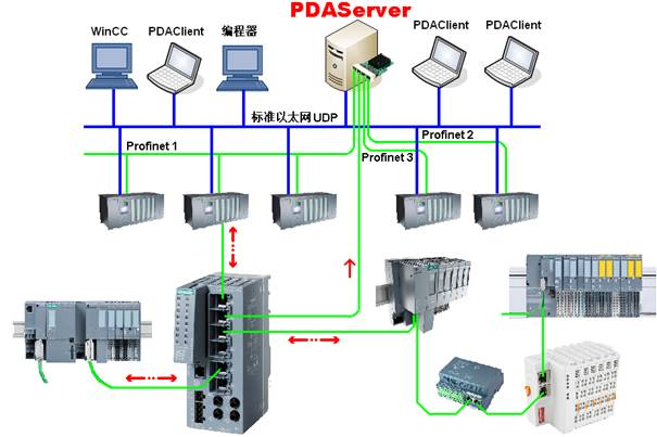
2 S7-1500 and slave drop data
collection scheme
The S7-1500 series PLC can achieve ms level data acquisition through Profinet(PDAServer as multiple PN slaves) or standard ethernet UDP, the PN switch may directly forward all slave data to the PDAServer, the system scheme is shown in the following figure.
|
|||||
|
|
|||||
|
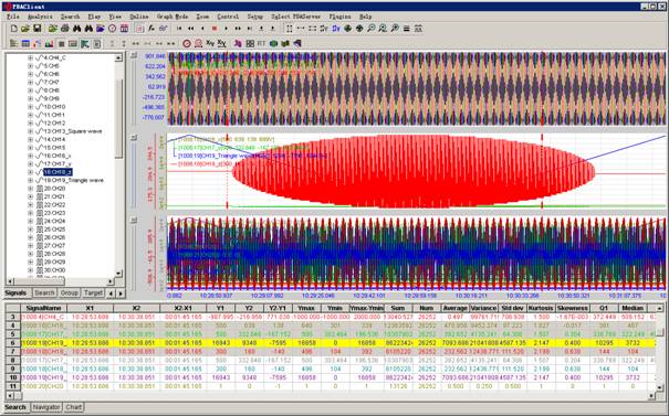
Apparatus test&Fault diagnosis&Quality analysis |
Millisecond data sampling Real-time data compression Capture signal instantaneous mutation |
||||
|
�������� �ٶ� ��Ѷ ���� ���� �Ѻ� ��� �Ա� ���� �й��Զ����� �й������� ������ ��Τ�� �������� �������վ �Ƿ�����վ �������վ Я�� ֪�� �й���� ��ұ���� ��ұ���� ��ұ�Ϸ� ��ұ���� ��ұ���� ��ұ���� ��ұ���� ��ұ���� �й����� ���� ���� ��� ���� �Ӹ� �� ��ICP��2025092850�� ��Ȩ����©Copyright:2025-2035. ��γ���¿Ƽ����人������˾ |
|||||
Develop communication protocol, Customized
analysis function, XinChuang domestic obsession
PDAServer
PDAClient