|
Profinet EIP EtherCAT
EGD UDP RFM RtEthernet Tc-net S7 Modbus OPC iso Ads Siemens
AB,GE,Mitsubishi,Beckhoff,MOOG,Schneider,ABB,Alstom,Driver,Domestic
PLC,Special Board QDR quality data
recording (digital steel coil) centimeter and millisecond level, supports
32+clients online Equipment testing, fault
diagnosis, quality analysis, ikoPDA CHPDA PLC-PDA, Full-stack Self-developed |
3rd PDA formats &
Rich proprietary features Global Standards,
Exceptional Value Simplified for Full Customization &
OEM with Open APIs Proven by Hundreds of |
|||
|
Process Data
Acquisition �C PLC-PDA -- Detailed analysis of
quality manage & industrial big data sources -- Full stack develop & Fully intellectual property
owned |
||||
|
|
||||
|
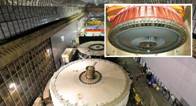
6 DCC - Digital Coil Conversion and full process quality management |
||||
|
20
Comprehensive data acquisition system for steelmaking plants |
||||
|
21 A
large amount of S7 communication causes network instability |
||||
|
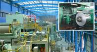
11 HDP - High frequency density and speed Data Platform
construction |
||||
|
12 HDC - Hot rolled high-frequency high-density
Digital steel Coil |
||||
|
26
Research Form for PDA System Configuration in the Steel Industry |
||||
2 PDA - data
acquisition and analysis system
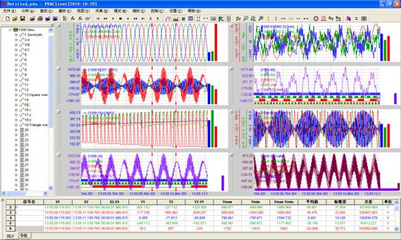
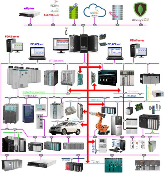
PDA (Process Data Acquisition) system is an industrial real-time platform with high speed data acquisition compression storage and analysis, online and offline analysis is its basis function, it's also a high performance general product at same time, it is a basic platform of industry 4.0 and big data. (1) Provide equipment test method for the equipment manufacturing factory (2) Provide effective methods of fault diagnosis and status detection for operation and maintenance of production plant (3) Provide a convenient tool for the analysis of dynamic process (4) provides the accurate basis for objection to the quality of product identification (5) Provide strong data support for the development of new products (6) Intelligent unmanned data recorder, radar, image recognition, speech recognition, deep learning, laser ranging, path planning, driving instruction, navigation and location, and equipment status 2.1
Overview of PDA system
The system can collect multiple units of PLC or controller data, the sampling period can be down to 0.05ms, the sampling points up to 100000 points, used to support the mainstream PLC, network, bus, hardware interface module, Multi-server and multi-client mode are supported, PDA drive may be developed cooperatively for special equipment, User specific analysis functions can be customized.
Figure 2.1 application interface 2.2 Fields
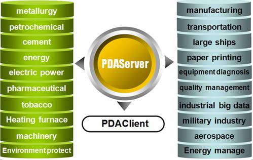
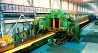
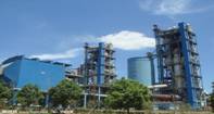
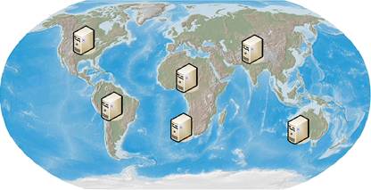
of application
Figure 2.2 Application fields
Figure 2.3 application fields of PDA systems 2.3 System
functionality and performance
2.4 Technology
parameters
PLC field bus and intelligent devices are supported.
|
|||||||||||||||||||||||||||||||||||||||||||||||||||||||||||
2.6
PLC, field bus and vendors
2.7
PLC protocol service of data platform
|
|||||||||||||||||||||||||||||||||||||||||||||||||||||||||||


|
No. |
Media |
Speed |
PDA data
acquisition scheme |
Example |
|
|
hardware |
Software protocol |
||||
|
1 |
RS-232 |
|
Common
serial port |
PDA
integrated |
Modbus |
|
2 |
RS-485 |
<=115200bps |
Convert
to RS-232 |
PDA
integrated |
|
|
3 |
RS-485 |
>115200bps |
Special
network |
PDA integrated API/OPC gateway Third party interface |
|
|
4 |
Special
RS-485
|
|
Special
network |
PDA integrated API/OPC gateway Third party interface |
Profibus-DP CAN DeviceNet |
|
5 |
Ethernet |
fast |
Common
ethetnet |
PDA
integrated |
Profinet |
|
6 |
Ethernet |
faster |
Special
network |
PDA integrated API/OPC gateway Third party interface |
EtherCAT |
|
7 |
Reflective Memory network |
faster |
Special network |
PDA integrated API/OPC gateway Third party interface |
GE Reflective Memory Siemens GDM TMEIC TC-net |
|
8 |
other |
|
|
|
|
PDA differently treats the different protocol understand for the same vendor in different periods or different manufacturers.
No program is needed for some PLC, Read directly data according to the variable address or symbol.
The real-time data interface is fully opened for the third party data platform which is convenient for the users to carry out data storage or processing neatly and diversely.
PDA system with a perfect communication protocol software development template may quickly develop unknown and future protocol.
2.7.2 Mainstream
automation protocols
2.7.2 .1 Process
automation
AS-interface • BSAP[Bristol Standard Asynchronous Protocol] • CC-Link Industrial Networks • CIP[Common Industrial Protocol] • CAN bus[Control Area Network](CANopen • DeviceNet) • ControlNet • DF1 • DirectNET • EPA Ethernet for plant automation • EtherCAT[Ethernet for Control Automation Technology] • EGD[Ethernet Global Data, GE/ALSTOM HPCi] • Ethernet Powerlink • EtherNet/IP[Rockwell ControlLogix/CompactLogix/MicroLogix] • FIP[Factory Instrumentation Protocol] • FINS • FF[FOUNDATION fieldbus](H1 • HSE) • GDM[Siemens Global Data Memory] • GE RFM[Reflective Memory, 5565/5576 VxWorks LogiCAD CoDeSys IsaGRAF]• GE SRTP[Service Request Transport Protocol, GE Fanuc 90/VersaMax/PACSystems] • HART Protocol • Honeywell SDS • HostLink • INTERBUS • IO-Link • Lightbus • Lonworks • MECHATROLINK • MelsecNet • Modbus/Modbus Tcp[Schneider-Modicon 984/Quantum��] • MP-bus[Modular Power Bus]• Optomux • PieP • Profibus • PROFINET • RAPIEnet[Real-time automation protocol for industrial ethernet] • Realtime Ethernet[Beckhoff] • SafetyBUS p • SERCOS interface • SERCOS III • Sinec H1 • Symotion • SynqNet • TMEIC TC-net • TTEthernet[Time-Triggered Ethernet] • WorldFip.
2.7.2 .2 Industrial
control system
EtherNet/IP-backplate[Rockwell ControlLogix/CompactLogix/MicroLogix] • GE SNP/SNPX • MTConnect • OPC[OLE for Process Control] • Profibus-MPI/DP • S7 Ethernet Tcp/iso[Siemens S7-400/S7-300/TDC/FM458].
2.7.2 .3 Building
automation
1-Wire • BACnet • C-Bus • CC-Link • DALI[Digital Addressable Lighting Interface] • DSI[Digital Signal Interface] • Dynet • Enocean • FIP • Idranet • KNX[EIB/BatiBus/EHSA] • LonTalk • Modbus • Modbus/Tcp • oBIX • VSCP • X10 • xAP[xAP Home Automation protocol] • xPL • ZigBee.
2.7.2 .4 Power-system
automation
CDT[Cyclic Digital Transmission] • IEC 60870 • (IEC 60870-5-101 • IEC 60870-5-102 • IEC 60870-5-103 • IEC 60870-5-104 • IEC 60870-6) • DNP3 • FIP • IEC 61850 • IEC 62351 • Modbus • Profibus.
2.7.2 .5 Automatic
meter reading
ANSI C12.18 • IEC 61107 • DLMS/IEC 62056 • DL/T645[Multi-function watt-hour meter communication protocol] • M-Bus • Modbus • ZigBee.
2.7.2 .6 Automobile
/ Vehicle
AFDX[Avionics Full-Duplex Switched Ethernet] • ARINC 429 • CAN bus(ARINC 825 • SAE J1939 • NMEA 2000 • FMS) • FIP • FlexRay • IEBus • IDB-1394 • J1587 • J1708 • KWP2000[Keyword Protocol 2000] • SMARTwireX • UDS[Unified Diagnostic Services] • LIN[Local Interconnect Network] • MOST • VAN[Vehicle Area Network].
2.8
Data acquisition and analysis view
Figure 2.7 Operation interface of data acquisition software
Figure 2.6 ~ Figure 2.23 is for operation interface of analysis software.
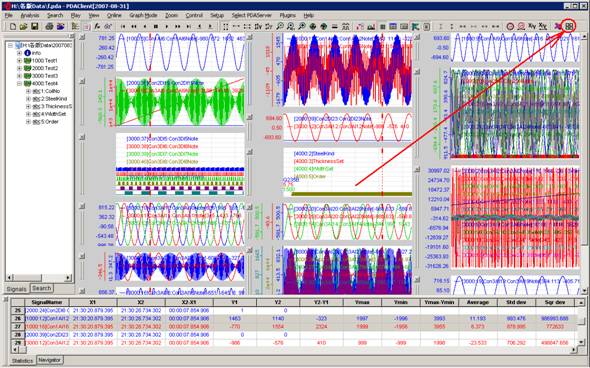
Figure 2.8 Main interface of analysis software and Multi column display of curves
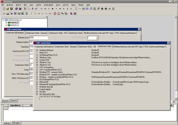
Figure 2.9 System configure
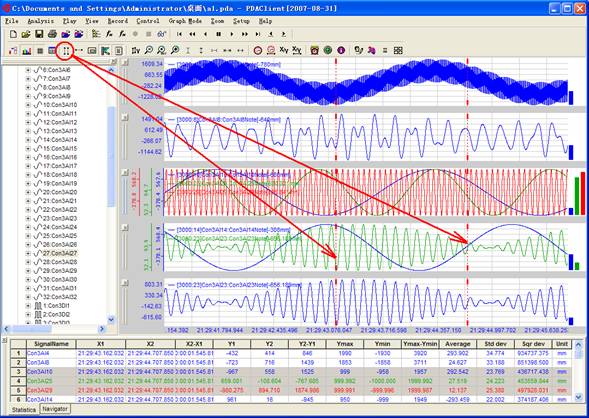
Figure 2.10 Dual x-axis mark
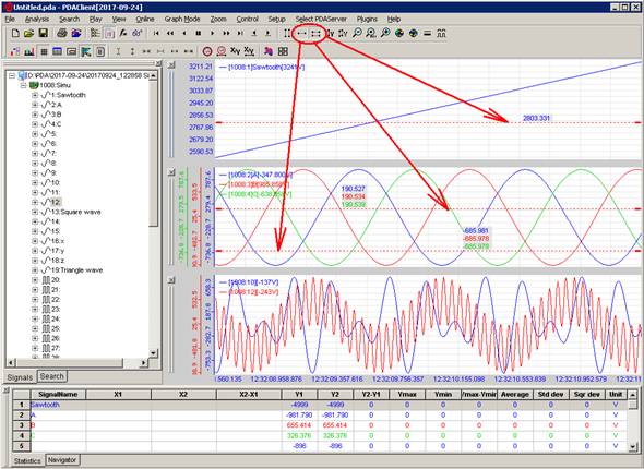
Figure 2.11 Dynamic y-axis and dual y-axis mark
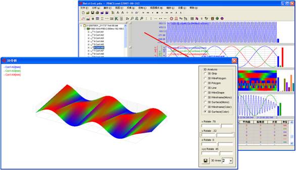
Figure 2.12 2D 3D view analysis
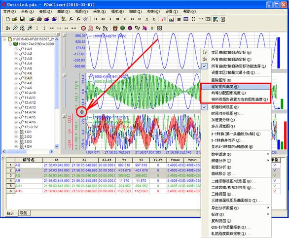
Figure 2.13 Height adjustment view
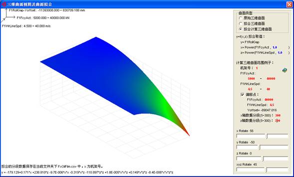
Figure 2.14 3D surface view and surface fitting
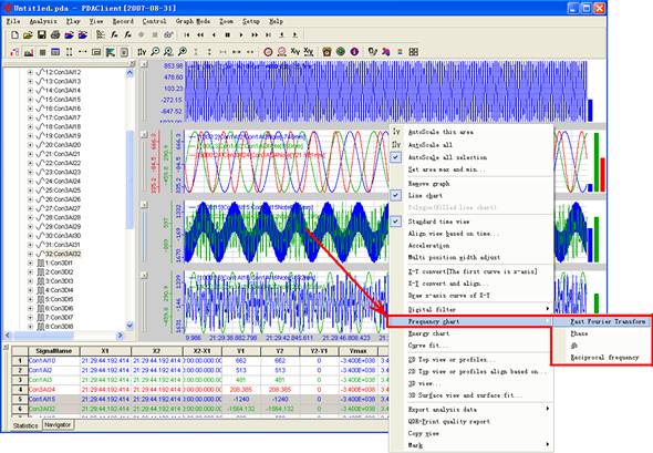
Figure 2.15 FFT- spectrum analysis
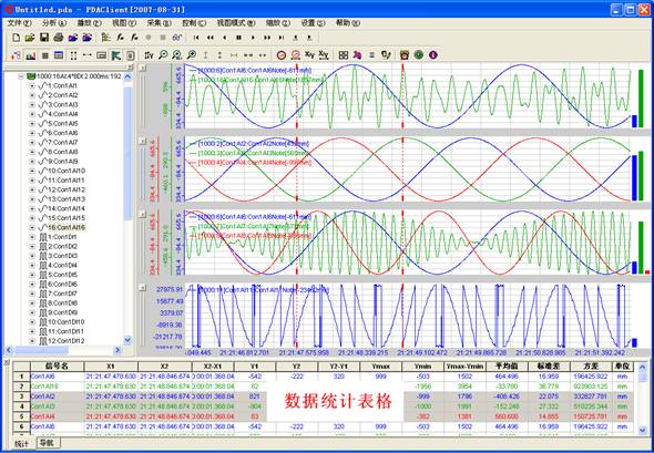
Figure 2.16 Data statistics
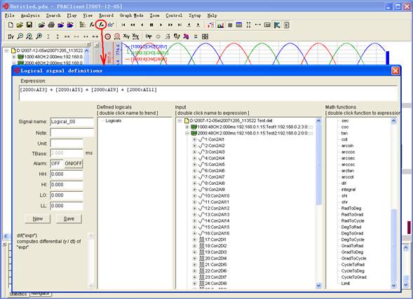
Figure 2.17 Logic signal - Expression
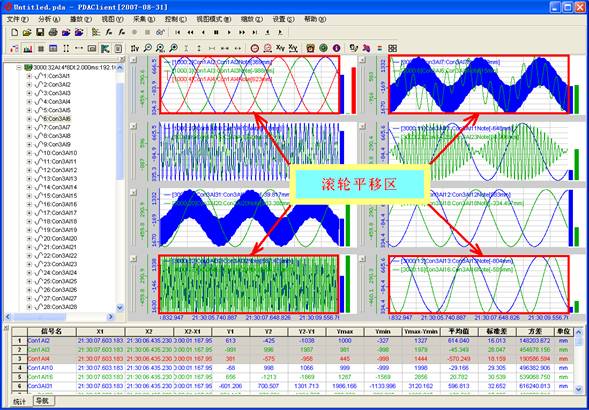
Figure 2.18 X-axis wheel trend figure translation
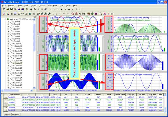
Figure 2.19 Y-axis wheel zoom and span
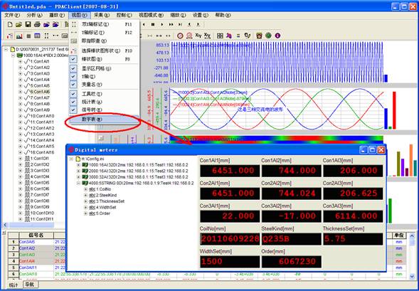
Figure 2.20 Digital table
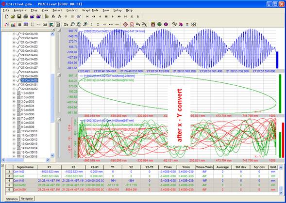
Figure 2.21 X-Y convert and align
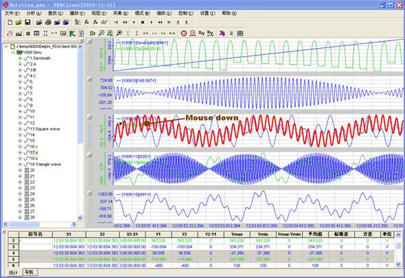
Figure 2.22 Curve annotation
Figure 2.23 Stiffness measurement of rolling mill
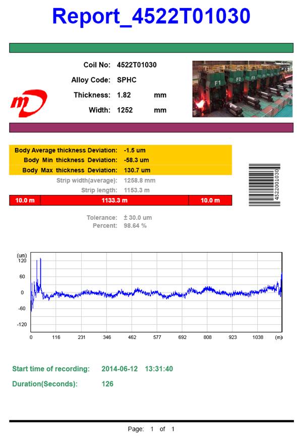
Figure 2.24 QDR Report of quality data record
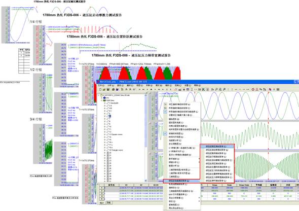
Figure 2.25 Performance test of large
hydraulic cylinder
2.9
WinCC-PDA FTView-PDA Web-PDA
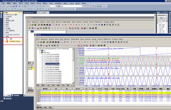
Figure 2.26 Call PDAClient.ocx in C#
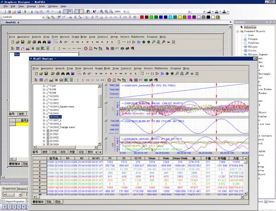
Figure 2.27 WinCC calls PDAClient.ocx
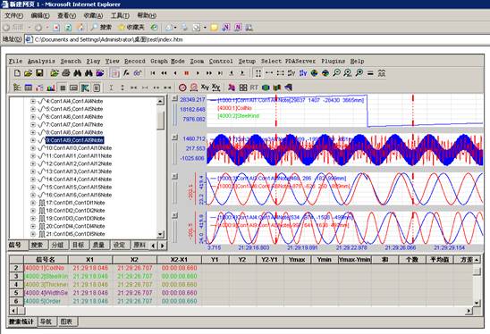
Figure 2.28 Call PDAClient.ocx in the browser
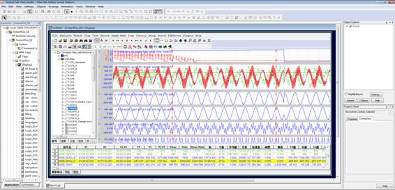
Figure 2.29 FactoryTalk View calls PDAClient.ocx
2.10 Using PDAClient under Linux
Connect to the Internet under Ubuntu and sudo apt install wine64 to install a 64 bit Windows emulator.
Copy PDAClient.exe to Linux, enter the directory where PDAClient.exe is located, right-click Open in Terminal, and run wine PDAClient.exe to directly open the PDAClient analysis tool.
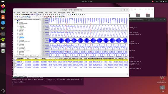
Figure 2.30 Using PDAClient.exe in Linux
2.11
pdaCloud
pdaCloud in Config.csv specifies whether pdaCloud.exe starts automatically.
pdaCloud.exe may gengeate ��day file list file, ��day second level data file, ��appropriate data file found and copy them and ��log file to the cloud synchronization folder specified by CloudDir of Config.csv.
pdaCloud.exe sends ��the day list file and ��log file to the Email specified by Config.csv.
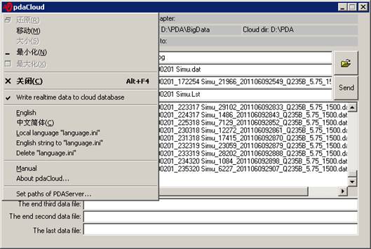
Figure 2.31 Prepare data for pdaCloud
2.12 Millisecond level high-speed data
acquisition for the entire factory
PDA supports data collection of 30000 points within 10 milliseconds. Slow or trigger signals in the entire factory can be saved at a unified high speed. If the data exceeds 30000 points, multiple PDA servers can be used. PDA servers reduce the frequency of the collected signals and write them to multiple relational databases such as SQL Server, MySQL, and ORACLE. Millisecond level signals are written to temporal databases such as InfluxDB. Other subsystems require real-time data to be forwarded by PDA servers at a high speed or reduced frequency.
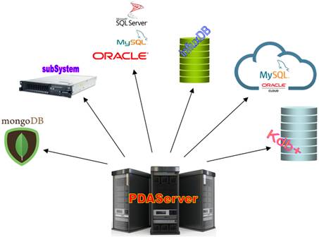
Figure 2.32 Data collected by PDA saved to database
2.13 High speed data forwarding
The PDA server adds a multi port network card. In principle, the data required by other systems is not directly connected to the L1 controller, but is obtained through PDA forwarding. Different network segments are forwarded through different network ports, which can save a lot of PLC resources.
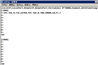
Figure 2.33 Setting up high-speed
data forwarding to multiple locations
Apparatus test&Fault diagnosis&Quality analysis
Millisecond data sampling
Real-time data compression
Capture signal instantaneous mutation
�������� �ٶ� ��Ѷ ���� ���� �Ѻ� ��� �Ա� ���� �й��Զ����� �й������� ������ ��Τ�� �������� �������վ �Ƿ�����վ �������վ
Я�� ֪�� �й���� ��ұ���� ��ұ���� ��ұ�Ϸ� ��ұ���� ��ұ���� ��ұ���� ��ұ���� ��ұ���� �й����� ���� ���� ��� ���� �Ӹ� ��
��ICP��2025092850�� ��Ȩ����©Copyright:2025-2035. ��γ���¿Ƽ����人������˾
Develop communication protocol, Customized
analysis function, Open data interface, XinChuang domestic obsession
PDAServer
PDAClient